Why Unsprung Mass is the Main Challenge for Tier 1 Companies

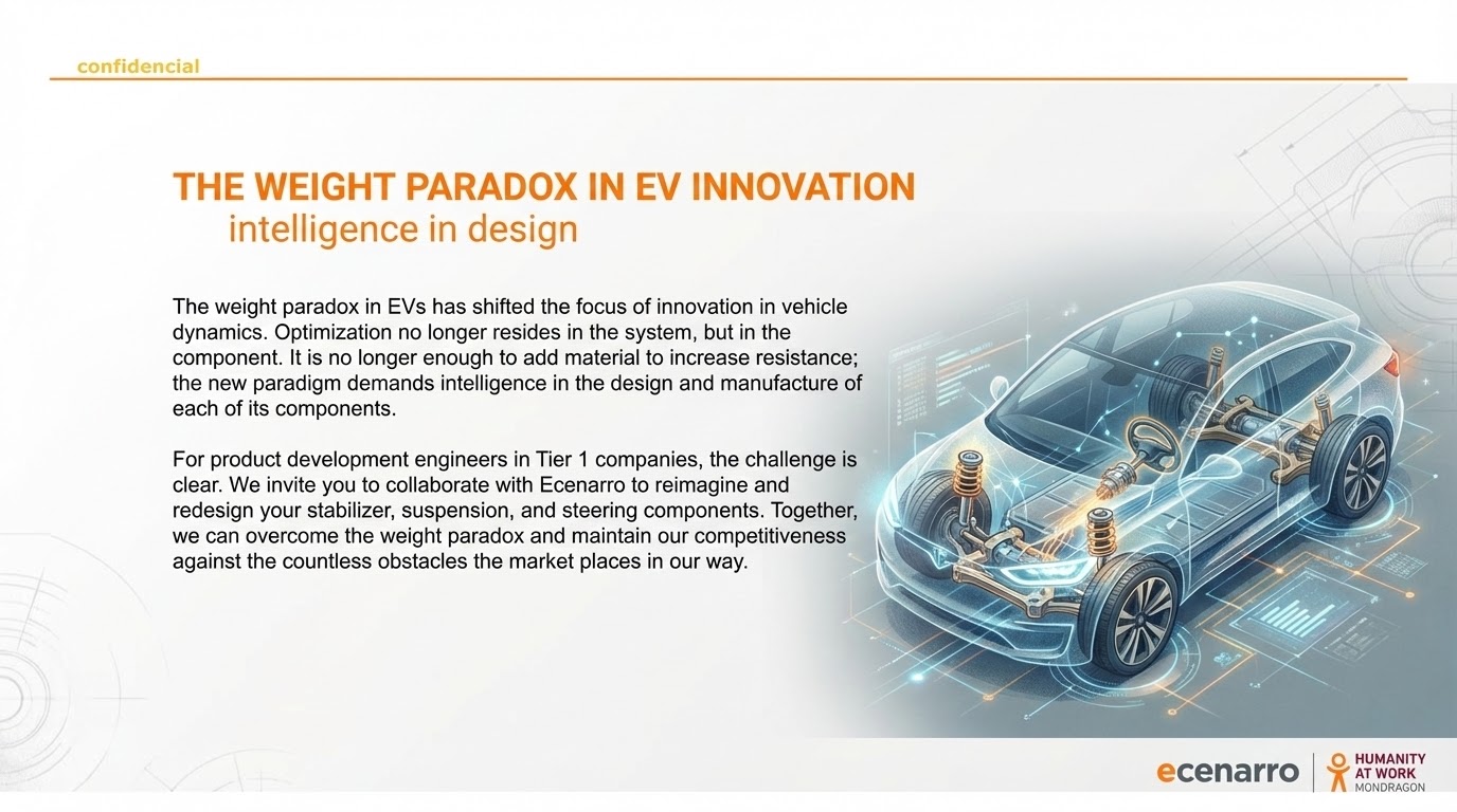
1. Introduction: The Fundamental Physics Defining the Driving Experience

In the transition towards the electric vehicle, weight has become the primary adversary. But while headlines focus on battery kilograms, the true battleground for vehicular dynamics and passenger comfort is being fought on a much more critical front: unsprung mass.

1.1. Defining the Concepts

To address the engineering challenges in the Electric Vehicle (EV) era, it is crucial to distinguish between two fundamental concepts: sprung mass and unsprung mass.

Unsprung components in the cold forging products

Unsprung Mass: The Critical Factor in Dynamics

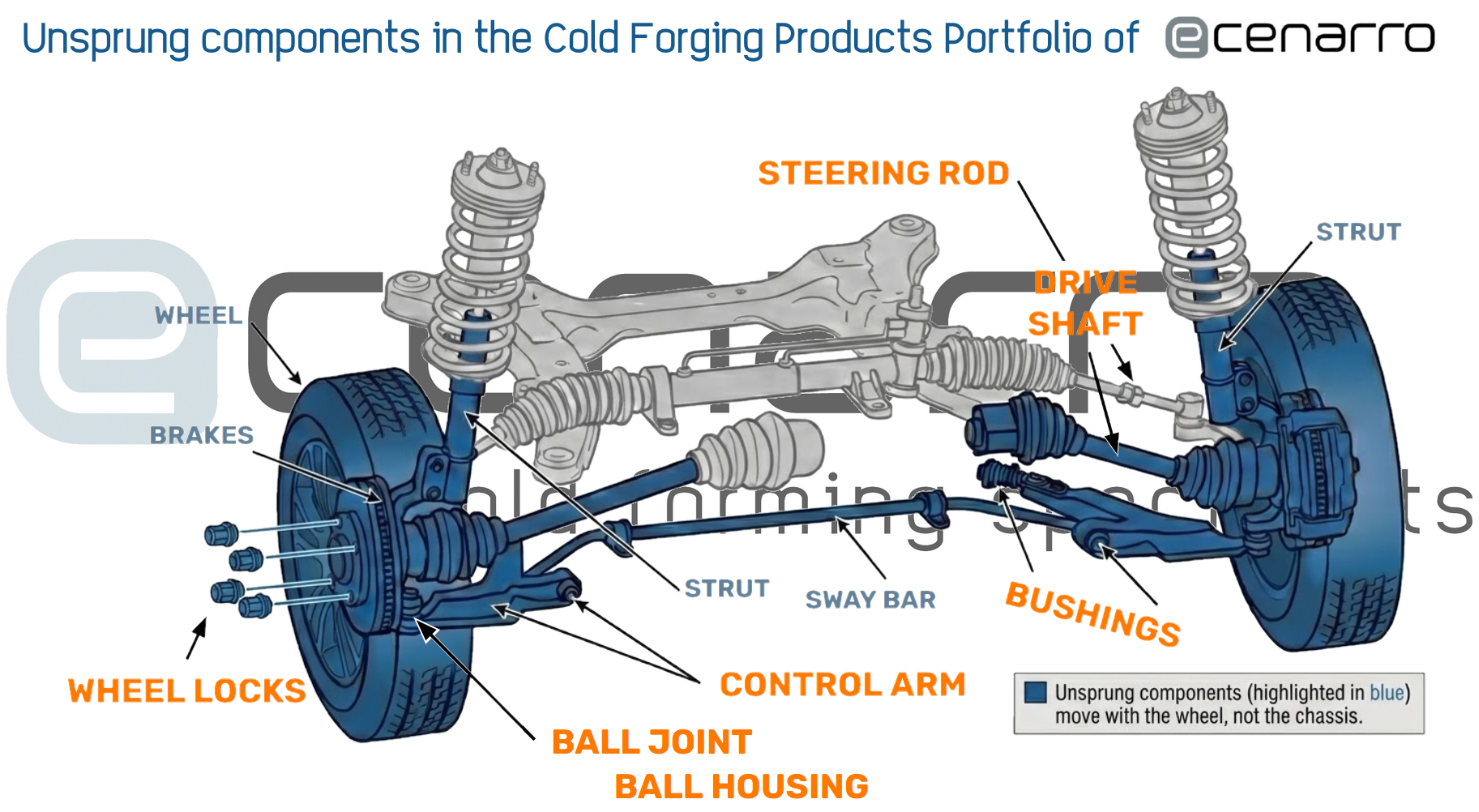
Conversely, unsprung mass refers to all components that are not supported by the suspension system. These elements are located directly between the road and the suspension. Typical examples include:

  • The wheels and tires.
  • The braking system (discs, calipers, and, in some cases, part of the wheel hub).
  • The suspension arms, bushings, and joints themselves that connect the wheels to the chassis.
  • In vehicles with drive axles, part of the differential and drive shafts (although this portion is often a hybrid or partially sprung in modern configurations).

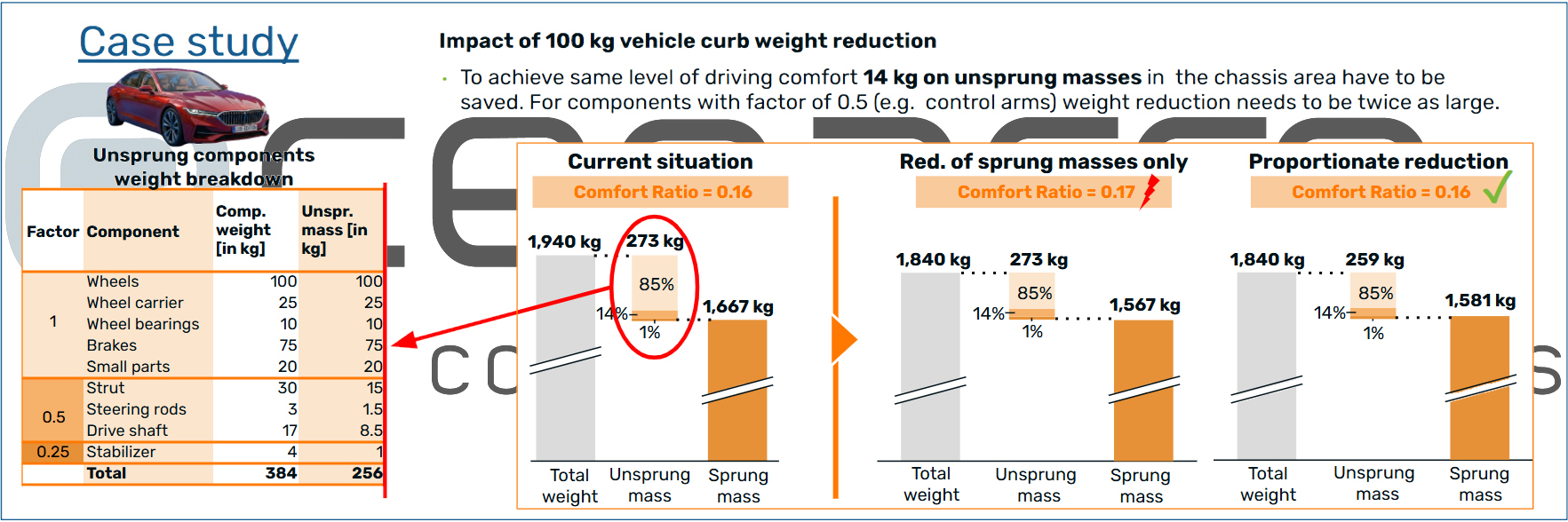
In the following example, for a sedan-type vehicle, the total unsprung mass can be around 275 kg. This breaks down into functional elements such as wheels (100 kg), brakes (75 kg), control arms (25 kg), and other parts (75 kg).

Sprung mass, Dynamics

1.2. The Physical Impact of Excessive Unsprung Mass

An increase in unsprung mass generates critical negative effects that directly compromise the development objectives of any modern vehicle. It is possible that the person reading this article has driven or ridden in a vehicle whose original 17″ wheels have been replaced with attractive 19″ aluminum wheels. Let’s look at the effect of increasing the weight of our wheels, which are an important part of the unsprung mass:

Compromised Grip and Stability

Compromised Grip and Stability:
Greater weight means greater inertia of the unsprung components, which prevents them from accurately following road irregularities. This causes load variations in the tire contact patch, reducing mechanical grip and, consequently, vehicle stability.

Degradation of Ride Comfort (NVH ratio):

Degradation of Ride Comfort (NVH ratio):
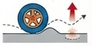
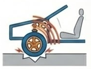
Instead of tracing the contour of a bump, a heavy wheel impacts it (the inertia of the ride keeps it in the air much longer), transmitting a high-frequency impact directly to the chassis. This sharp blow is perceived by the passenger as harshness and forces manufacturers to reduce the damping level to make it “softer”.

Generation of Discomfort and Motion Sickness:

Generation of Discomfort and Motion Sickness:
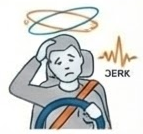
With a high sprung mass and softer suspension, the effect of overacceleration (jerk) arises, which is the rate of change of acceleration and is a key indicator of discomfort, as studies confirm that passive occupants are especially susceptible to these stimuli which ultimately cause many people – not the driver – to suffer from motion sickness during the trip.

The disproportionate impact of this mass is not merely qualitative. Case studies quantify it: to compensate for a 100 kg reduction in a vehicle’s sprung mass (a common lightweighting goal) and maintain the same level of ride comfort, it is necessary to reduce the unsprung mass by around 15% of that reduction. This relationship demonstrates that every gram removed below the vehicle’s springs has a multiplier value in vehicle dynamics and occupant comfort.

2. The Electrification Challenge: A New Weight Equation

The transition to electric vehicles has magnified the unsprung mass problem by introducing a significant increase in the vehicle’s total weight.

2.1. The Battery Pack Factor

The battery pack is the main contributor to this increase. For example, the battery pack of a
Volkswagen ID4 weighs 490 kg, that of a Tesla Model Y weighs 775 kg. and that of a BYD Seal
weighs 560 kg, adding the equivalent of five or more adult passengers before a single person sits in the vehicle.

2.2. Consequences for Chassis and Component Durability

The substantial increase in the total mass of modern vehicles, primarily driven by electrification and added features, has a profound and detrimental effect on the chassis and suspension system. This augmented heft directly translates to much higher cyclical loads being imposed on all associated components. These parts, including crucial elements like control arms, tie rods, and shock absorbers, already operate deep within the very high cycle fatigue (VHCF) regime, which typically involves a life expectancy exceeding $10^8$ load cycles.

The current escalation in mass-induced stress threatens to reverse decades of painstaking advancements in material science, component design, and durability engineering within the automotive sector. Specifically, the increased stress levels accelerate material degradation and crack initiation. In critical, load-bearing components such as ball joints—which serve as the pivot points in the steering and suspension—fatigue caused by these intensified cyclical loads is no longer just a contributing factor, but the primary and predominant cause of catastrophic fracture and failure. This necessitates a fundamental reassessment of current material specifications and design safety margins for all unsprung and sprung mass components.

3. The OEM Dilemma: The Unsprung Mass Paradox

This new weight equation presents a fundamental dilemma for manufacturers (OEMs) and their Tier 1 suppliers.

3.1. The Logical Sequence of the Problem

The conflict can be summarized in an inevitable logical sequence:

  1. EVs require heavy batteries, which drastically increases the vehicle’s total weight.
  2. This weight forces engineers to design more robust, larger suspension components to manage the increased structural loads and ensure durability.
  3. Conventional methods for increasing robustness involve adding material, which increases the weight of these components and, therefore, the unsprung mass.

3.2. The Inescapable Conclusion

The fundamental goal of chassis engineering is to maximize the ratio between sprung and unsprung mass. Herein lies the EV paradox: the traditional approach to ensuring durability directly conflicts with this principle. By making suspension components heavier to support the battery weight, the driving experience is degraded, and maneuverability is compromised.

This forces us to abandon the traditional engineering manual. The only way forward is a fundamental divorce between strength and mass: advanced lightweighting is not an option, it is a design imperative.

4. The Solution from Ecenarro: Design For Cold Forging (DFCF) Process

The solution from Ecenarro Desing for cold forging process

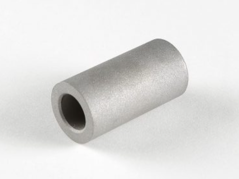
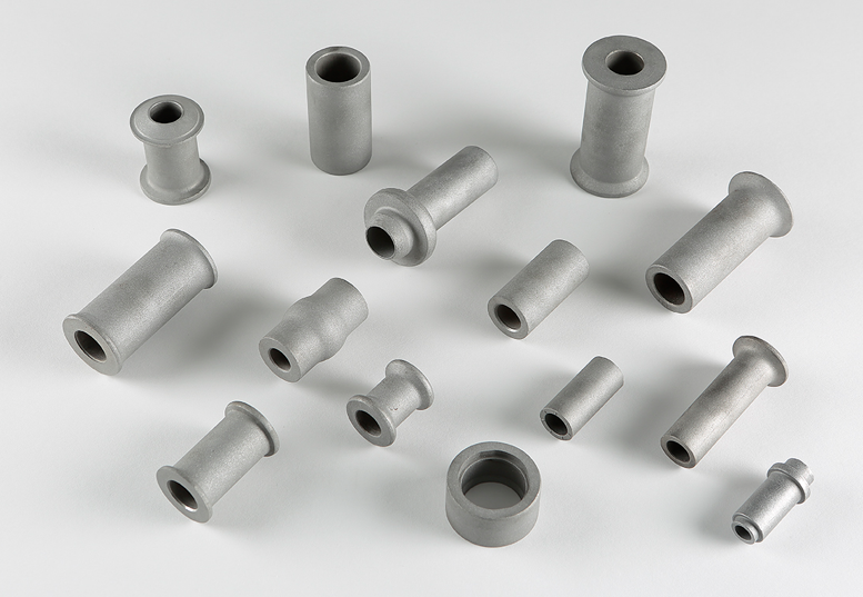
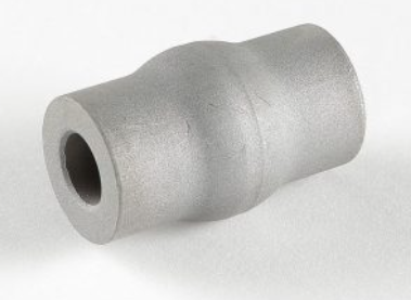
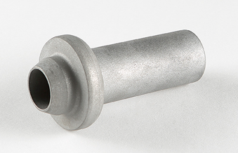
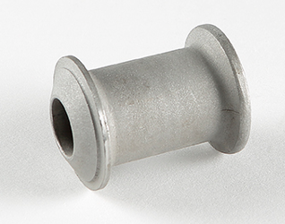
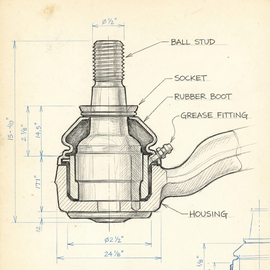
At Ecenarro, we have directly addressed this paradox, focusing on the redesign of critical unsprung mass components. Our focus is on the family of ball joints, ball pins, or ball studs. This part is fundamental to allow angular movement in the suspension and steering, connecting the control arms with the rest of the system for an agile and safe response. Since control arms represent approximately 5% of the total unsprung mass, optimizing their key components, such as the ball pin, is a high-leverage activity.

Our technological approach is based on two fundamental pillars:

  • Advanced Materials Science: We specify and process STANDARD alloys not only for their nominal strength, but based on their work-hardening capacity, optimizing their microstructure to maximize resistance to fatigue crack initiation and propagation, while meeting the rest of the mechanical requirements.
  • Innovative DFCF (Design For Cold Forging) Process:
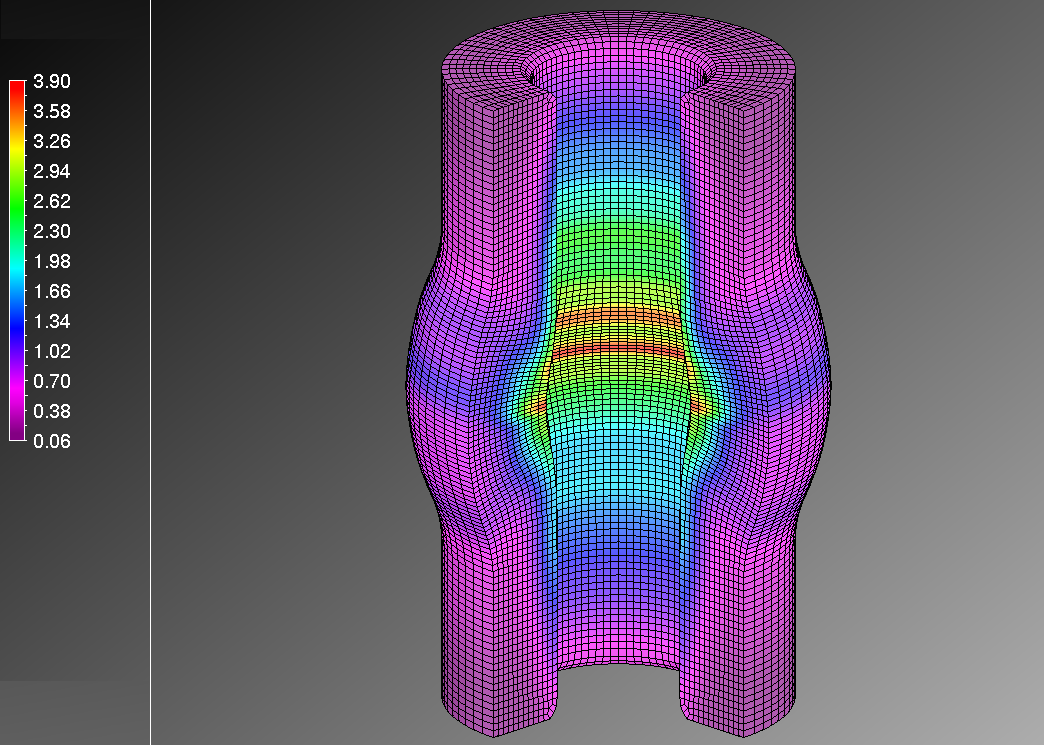
    • By pushing cold forming to the limit, our cold forging processes allow the design of deformation strategies focused on maximizing the mechanical properties of the products, taking the hardness map to the highest possible in each case, specifically for each part, generating products in which some areas reach up to 1050 MPa of strength directly out of the forging process.
    • Generating processes that combine Cold Forging with heat treatment cycles that elevate the performance of the products to achieve resistance values close to 1,400 MPa.

5. Competitive Advantages for Tier 1 Companies

The Ecenarro solution offers clear and measurable competitive advantages for product engineers at Tier 1 companies:

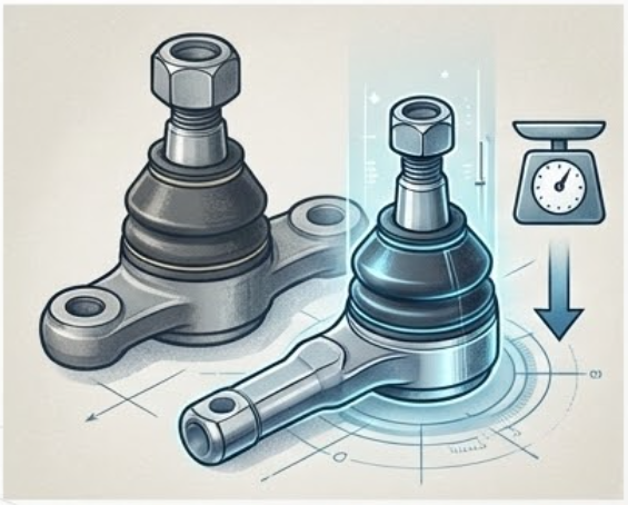
1.Reducing Product Dimensions:
Ecenarro, in collaboration with its innovation ecosystem, is continuously seeking standard steels or new heat treatments to apply to conventional steels, to offer the market ball joints that provide mechanical and fatigue resistance equal to or superior to that of components manufactured with conventional processes, but with a reduced weight. This allows for reduced unsprung mass without compromising durability or safety.
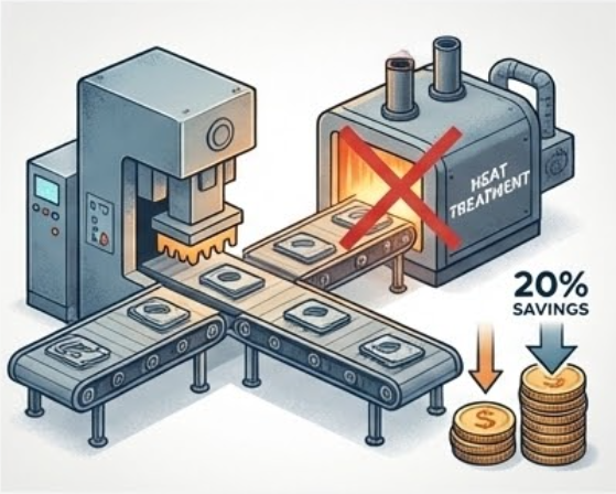
Cost Efficiency:
Through the use of high-deformability and high-work-hardening steels, Ecenarro has successfully developed forging processes that produce products that do not require heat treatment, reducing the product cost by around 20%.

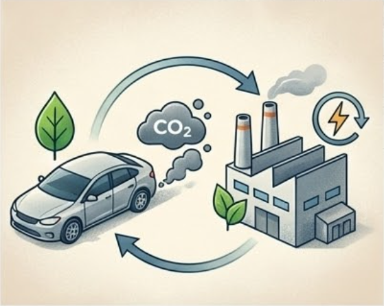
Integrated Sustainability:
Our solution provides environmental benefits on two fronts. First, lighter components improve vehicle energy efficiency. Second, our manufacturing processes without heat treatment consume less energy, reducing the carbon footprint per component.

6. Conclusion: Innovation Resides in the Component

Silentblock: the importance of the invisible.

An unknown friend

For the general public, the vibrations transmitted from the ground and from the powertrain to the passenger compartment are familiar. One might think that all the work of vibration damping might solely lie with the shock absorbers, even with the seat upholstery. Nothing could be further from the truth.

Advertising brochure, note the effect of inflation.

They have been with us for some time, specifically since 1936. The Chrysler company presented a vehicle of one of its sub-brands, Plymouth, with a 6-cylinder engine lying on the chassis on 3 points. These points were fitted with a rubber block, which mitigated the vibrations transmitted to the frame of the vehicle.

They called it “floating power”, and it became an instant success. All manufacturers replicated the concept and have evolved it to this day. While the rudimentary Plymouth had 3 silent-blocks on the engine, now commonly referred to as an engine mount, a current vehicle can be equipped with more than 30 silent-blocks of different types distributed throughout the various systems of the vehicle.

But… What is a silentblock?

A silentblock is a mechanical element that avoids having an infinite stiffness in the connection of two stiff elements. Instead, it maintains this stiffness under certain parameters. This is achieved by adding an interface of a low stiffness material between two stiff elements.

Earlier I mentioned the invention of the silent-block in 1936, but if we go to the concept, it is something earlier. Millions of years earlier, to be precise.

We all carry a silent-block with us, it’s called a meniscus. We always remember it… when it fails.

The meniscus has the function of damping impacts and vibrations to protect the bone structure. In the context of a vehicle, a silent block plays a dual role in ensuring both structural integrity and passenger comfort. Here the low stiffness material is natural or synthetic rubber instead of cartilage tissue and the high stiffness elements are two metallic elements, such as steel or aluminum, instead of bone tissue.

This stiffness must be limited within certain parameters. Not only to a single load, also to alternative loads sustained over time, which are called dynamic loads.

But stiffness is decomposed in several axes: Radial, Axial, Torsional and Conical (o Cardanic). 

When we talk about radial stiffness, we refer to the resistance that the component offers to deform when we apply a displacement x perpendicular to its axis

The more resistance it offers to deformation, the stiffer it will be. This applies to all cases.

When we talk about axial stiffness, this time we are talking about the resistance that the component offers to deformation when we apply a displacement parallel to its axis. 

Let’s look at the component from one side to see the concept of torsional stiffness. Here, we are talking about the resistance that the component offers to deform when we apply an angular displacement ⍺ in a plane perpendicular to its axis.

And finally, we will talk about conical stiffness. Here, it will be the resistance that the component offers to deform when we apply an angular displacement β in a plane parallel to its axis

And what is all this for? Well, they are the parameters that will be used to define the typology and geometry of the parts of a silentblock.  

For example, what happens when we want to have high radial stiffness while maintaining torsional stiffness? We add an intermediate ring:

And what happens when we want to have a high radial stiffness and a low conical stiffness, admitting a certain degree of articulation? Using a spherical bushing.

There are a multitude of cases and different solutions. Moreover, there is no single solution to a single problem.

The geometry of a silentblock is also defined by its boundary conditions, i.e., the available length, the connecting screw size and, sometimes, the required contact surface.

The core of the silentblock

Every silentblock has a metal core. It may be called bushing, innercore, inner bushing, all to refer to the same component.

Geometrically they are defined both by the required stiffness characteristics and by the boundary conditions. The simplest possible geometry is a straight tube, which can be obtained by cold forging, tube cutting, or machining.

A machining process can be useful for prototypes, whereas a tube cutting process could be appropriate in low and medium series for low-demanding products.

Cold forging technology is the best choice for medium and large series, thanks to its high repeatability and production speed, which results in a combination of performance, quality and cost that cannot be matched by other technologies.

In addition to the straight bushing, there are several more elaborate types, which must inevitably be manufactured by cold forging when we are talking about medium and large series. We can find bushings with one or more flanges, cone ends or with knurls to lock the angular position of the elements to be fixed.

Since there is no single solution to the same problem, it is the job of an engineering team and a purchasing manager to find the best possible solution in terms of performance, quality, cost and service.

How can a silentblock bushing supplier help in the product design phase? By optimizing both geometry and materials to achieve an optimum balance. 

The supplier’s expertise in the manufacture of any type of geometry will help in the correct definition of the product. In many cases, making modifications that are not relevant to functionality helps to economically rationalize a product and to launch it with less risk.

On the other hand, when a designer thinks about what materials to use for the core of that silent-block, the first thing to know is what stress that component will withstand.

To calculate this stress, you must know the forces to which the silentblock will be subjected. In this case, the most relevant is the tightening force applied by the connecting bolt between the silentblock and the component to which it is attached.

If the core is plastically deformed, the silent-block will not be properly tied between the elements, and the connecting bolt may loosen and compromise the integrity of the system. Knowing the force to be withstood and the geometry of the bushing, one can know the maximum stress the material must withstand. 

Given this limit, an engineer would typically visit a material standard and select one whose yield strength exceeds the maximum stress to which the material will be subjected.

While this may appear to be the most appropriate approach, when we are talking about components whose geometry has been achieved by plastic deformation, it becomes a methodology that technically ensures performance but is not cost-optimized. And when this happens, that product does not reach the market.

Fortunately, there are good news. There is a phenomenon called work hardening.

This strengthening occurs because of dislocation movements and dislocation generation within the crystal structure of the material. As long as the material saturates with new dislocations, there is an increasing resistance to the formation of new dislocations.

The greater the plastic deformation of the material, the greater the strength. It is not uncommon to be able to double the strength of the base material. This leads to being able to obtain resistances of high alloyed and expensive materials just using low alloyed, inexpensive steels. This is something that can be studied using specific simulation tools.

Therefore, one way to optimize the cost of the assembly is to seek the optimum ratio between the amount of rubber and steel to be used, being able to obtain the desired mechanical properties by using less steel and using inexpensive alloys.  

Having the support of a supplier who masters all these keys, instead of only looking for the best pure cost based on a closed definition, is essential for achieving success in the long term.

Manufacturing bushings by cold forging

By cold forging, the final geometry of a bushing is obtained “almost” only by plastic deformation of a piece of wire calibrated in diameter and cut to a certain length.

When we say “almost”, it is because there is one exception: the metal slug.

When starting from a solid wire, there is no possibility of obtaining a through-hole geometry just by plastic deformation. 

Instead, the material is processed until the final geometry is obtained and, by a cutting station, a metal slug is removed. This metal slug’s diameter equals the bushing inner  diameter and its thickness is in many cases equivalent to the wall thickness of the bushing.

Regarding the possible geometries, it is possible to add a knurling on the front faces:

Geometries with one or two flanges:

Or, for example, with a spherical central part:

Other geometries such as cone-shaped ends or other special geometries can also be made.

Key benefits of cold heading:

  • Minimal waste. A very low % of the material is wasted.
  • High production capacity and easy scalability. With speeds up to 120 parts per minute, a single former can supply large volumes of components.
  • High dimensional accuracy and repeatability, particularly in diameters and tooling dependent geometries.
  • Improved mechanical properties, allowing the use of low alloyed materials.
  • Low energy consumption, resulting in a reduced CO2 footprint.

For sectors such as the automotive industry, where the production of millions of units per year with minimum tolerances is required, this technology is particularly suitable.

Your key player

When looking for a silent-block bushing supplier, it is important to have a key partner. 

That key partner might be:

  • Someone who advises you in the design and product definition phase to find the optimal solution to your challenge.
  • Someone who has manufacturing lines dedicated to this type of product, offering a competitive solution in quality, cost and lead-time.
  • Someone who has engineering resources with the ability to develop a robust production process reducing the risks of launching new projects.
  • Someone who can manufacture in both Europe and North America with equivalent production resources to reduce risks.
  • Someone who has a long-term orientation in customer and supplier relationships.
  • Someone who has investment capacity and the backing of a group such as the Mondragon Group.
  • Someone, in short, like Ecenarro.

Conclusion

A well-designed component with a well-chosen supply chain reduces costs, minimizes risks, avoids hassles, saves time and reduces anxiety for those responsible of these decisions.

At Ecenarro we are available to help you from an early conception stage, providing our expertise, quality and efficiency.

If you want to see who we are and what we do, we invite you to see our Web, LinkedIn or Newsletter.


How the US trade war and tariffs affect the automotive component industry?

Introduction

The trade war initiated by the United States is significantly impacting costs in the automotive component industry and has triggered a widespread search for suppliers capable of avoiding the tariffs threatened by Donald Trump. This situation is increasing the level of uncertainty in the market because while tariff announcements are applied immediately, affecting short-term competitiveness, companies have to position themselves and make decisions that, at best, affect the medium term.

Apparently, Donald Trump’s objective is to rebuild local value chains, but this requires enormous investments, long-term horizons, and a certain stability in the rules of the game. Large investments require more than five years, longer than a political cycle, and initially involve even more imports, also subject to tariffs. If companies suspect that the tariffs will be reversed with the next change in administration, they will have no incentive to make risky and costly capital commitments.

Currently, the best alternative seems to be having production facilities in Mexico. Thanks to the USMCA (United States-Mexico-Canada Agreement), the trade agreement between the United States, Mexico, and Canada, companies can avoid tariffs and maintain cost competitiveness without compromising the quality and service of components for automotive clients. In this article, we explore why sourcing from Mexico is the best strategy and how Ecenarro can help you reduce the risk and uncertainty of your project.


What products has the United States imposed tariffs on or threatened to?

In recent months, the United States has implemented tariffs on various imported products, particularly from regions or countries such as the European Union and China. In addition to sectors like metallurgy or electronic components, it has mainly affected the automotive component industry with 25% tariffs on European products. The new round of US tariffs increased tariffs on China by 145%

Mexico, however, has been excluded from the latest tariff announcement, as has Canada. Both countries are covered by the USMCA, which establishes favorable trading conditions.

Products manufactured in Mexico that meet the requirements of the treaty will remain exempt from tariffs, while those that do not comply will be subject to 25% tariffs in the case of automotive components. This situation puts production plants located in Mexico at an advantage compared to other economies that will face higher costs to access the North American market.


Key advantages of having a supplier with manufacturing in Mexico.

Having a Mexican supplier offers significant advantages for automotive Tier suppliers located in North America. Mexico is an attractive option for companies seeking to maintain their competitiveness without sacrificing quality.

  • USMCA Benefits: This treaty allows for tariff-free trade between the United States, Mexico, and Canada, provided that value regeneration requirements in the territory are met, as Ecenarro does.
  • Competitive Production Costs: Manufacturing in Mexico offers competitive labor and operating costs, which, combined with European technological expertise, creates a very appealing combination for Tier 1 or Tier 2 automotive suppliers with global needs.
  • Geographic Location and Supply Chain Efficiency: Proximity and presence in the North American market become a strategic advantage by reducing delivery times and optimizing logistics compared to Chinese or European options. You reduce the risk of obsolescence and fluctuations in maritime transport costs.
  • Exchange Rate: Transactions are conducted in US dollars, thus avoiding fluctuations in local currencies and exchange rate variations of the Euro and the Yuan.
  • Industrial Infrastructure: Mexico has a skilled workforce and continuously improving communications, facilitating an efficient supply chain. It also allows for scaling operations according to business needs.


How to reduce risks when switching from a Chinese or European supplier to a Mexican supplier?

The key aspects to consider when switching from a European or Chinese supplier to a Mexican source of supply are the following:

  1. Have a global supplier with experience in the automotive market, with more than 10 years of production experience in Mexico and knowledge development in Europe.
  2. It is important that they have engineering resources and the capability to ensure robust production processes that avoid risks in launching new developments and components in Mexico.
  3. That they have production resources equivalent to those in Mexico in other locations to support continuous improvement and temporarily cover potential incidents at the beginning of Mexican production.
  4. In addition to their core technology, that they integrate complementary secondary operations in Mexico to reduce costs and improve production lead times.
  5. That they have a long-term orientation and a clear commitment to development and permanence in the North American market.
  6. That they have the capacity for future investment and the backing of a business group such as the Mondragon Group.


Conclusion

A new trade balance will be generated in business with the US. Faced with this, companies have two options: one is reactive and defeatist, which has a very short lifespan, and the other is the one we choose at Ecenarro, which is resilience and action in the search for solutions and alternatives.

From our plant located in Celaya, Guanajuato state, we offer a competitive product based on cold forming technology, with engineering and knowledge developed over decades in Europe, ensuring robust and high-quality processes. Our world-class production facilities, such as the forming and machining equipment we use in our Mexican plant, position us as a preferred partner for Tier 1 or Tier 2 automotive companies seeking a specialist supplier of ball joints, bushings, shock absorber pins, wheel bolts, and steel pinions or gears made by cold heading.

If you want to explore how we can collaborate, contact us and let’s talk about how we can be your strategic partner in the North American market.


From machining to cold forging 

Cold forging machines are capable of manufacturing precise metal parts for automotive, aerospace, railway and heavy vehicle industries, among others. In this post, we will explore the several advantages of this technology in comparison with traditional machining manufacture and the design considerations that must be taken in order to smoothly transfer our designs from machining to cold forging . The devil is in the details

What are the advantages of cold forging?

Cold forging is a high-speed process that consistently meets the required resistance values and geometry accuracy of the components, making it a very suitable process for high volume productions.

These machines are fed with room temperature steel rod coils of a given diameter (sometimes even other non-circular geometry) which is then sheared, transported and shaped progressively in various steps by applying pressure using precisely shaped toolings.

Many times, we associate cold forging with standard screw geometries; however, it is possible to obtain highly complex parts that would otherwise require machining centers to complete them.

Cold formed parts can be finished with heat treatments, simple secondary machining operations, thread or groove rolling, and coatings.

The following advantages can make you consider transferring your production or supply of components from machining to cold forging:

Cost-effective

Both cold forging and machining are viable processes for different applications and needs. When the production volume reaches around 100,000 parts per year, we can start considering whether the geometry of our part can be cold formed. The initial investment in tooling development will be easily compensated by the savings in material and part cost when manufacturing in large volumes. The repeatability and speed of cold forging make up for the necessary production costs. Depending on the geometry, smaller annual volumes may also easily pay off.

Reduced lead time

Cold forging machines work at 100-150 parts per minute (that’s around 2 parts per second!), whereas machining lathes require longer times to finish the component with a higher dependency on the part geometry (1-2 parts per minute can be usual). Some geometries can be challenging to obtain by cold forging and a secondary machining operation may be necessary, however, we still have savings compared to machining the whole component because of the speed and the amount of material used, which takes us to the next advantage; scrap savings.

Less scrap

Cold forging is a sustainable process since the material is deformed instead of cut. This means that when we shear a portion of the coil, the whole blank is used as part of the final component. When the blank is progressively pressed into the dies, the initial shape can enlarge or reduce its diameter, adjust the length of different portions of the part and include other geometries such as hexagonal heads or sockets. Think of it as pressing a portion of Play-Doh inside a die, its shape will change but the amount of material is constant. Without a doubt, the metallic materials we cold forge are not as soft as Play-Doh, which implies several limitations in terms of material deformation, and the geometry progression must fulfill certain rules.

When a hollow part is needed, a small portion of the part (called slug) must be cut, generating some scrap.

However, when machining a part, the initial material required must be at least the size of the biggest diameter and length of the final component, in order to cut the desired shape out of it. You can imagine this as a marble sculpture from where you take lots of material out of before revealing the final product.

Mechanical properties and geometry accuracy

Since the material we cold form is progressively deformed, the deformation itself causes hardening, resulting in improved mechanical properties in the final part compared to the initial blank. This effect is known as work-hardening. It occurs due to the deformation of material fibers, which adapt to the shapes of the dies at each step. However, in machined parts, the material is cut to achieve the final shape, but no deformation is applied. Therefore, the fibers remain as in the initial material and do not gain additional strength. 

With the right choice of material and thanks to the work-hardening effect, secondary operations such as heat treatments can be avoided, bringing a competitive part with the expected properties into the market.

The accuracy achieved in a cold-forged part enables finishing parts without the need for additional processes and is suitable for many applications; automotive, general industry, off-highway… It all depends on the geometry of the component, but we know that lengths can meet tolerances of ±0,10mm and many diameters ±0.02mm. This level of precision in diameters is consistently achieved due to the excellent surface finish. In fact, we have been able to develop parts where secondary grinding operations for diameters have been eliminated thanks to the precision of cold forging.

So, are my components suitable for cold forging?

Now that we know more details about the advantages and applications of cold forging, it is time to consider whether it is feasible to cold form the parts we currently manufacture by machining. This way, we will have lower-cost parts due to high production speed that improves the lead time of the part and reduced scrap. This will allow us to offer more competitive solutions in a market like the automotive industry, where it is increasingly difficult to stand out.

Material deformation is the key to designing a suitable process for the geometry and characteristics of the final component. Therefore, it is possible that the design of the machined component must be slightly adapted to continue meeting its functions and requirements while optimizing the process for cold forging.

The devil is in the details —this means that considering these details beforehand will allow us to transfer our parts from machining to cold forging without issues and achieve stable mass production in a short time.

It is important to consider that this technology shift brings several advantages, so it is worth reviewing the functionality of the current part, its role in the assembly where it is mounted, and the essential geometric requirements needed in each area.

As you can imagine, the pressures in the cold forging process are very high, since the material deformation occurs at room temperature, and some geometry changes can be considered extreme. However, the deformation itself can heat the material in some cases up to almost 200ºC, so caution must be taken when handling parts that have just come out of the machine.

The tools used in cold forging have highly demanding characteristics to withstand these cyclic pressures, so anything we can do to improve tool life is beneficial for production stability and dimension accuracy, reducing downtime and tooling costs.

Let’s go into detail

At Ecenarro , we have been analyzing our customers’ blueprints for years. Many times, we realize that designs are intended for machined parts, and we proactively indicate the details that must be modified to make them feasible for cold forging. Without a doubt, the functionality of the part must remain just as demanding, but we can identify non-critical areas
where changes are feasible and simulate them before purchasing any tools to verify their potential. This can make the difference between being able to cold form the parts or not, with all the benefits that this entails!

If we consider the following design tips, we can verify whether our machined part is directly “cold-formable” or detect what can be adapted to make it feasible. Are you ready to dive into the details that will successfully translate your designs from machining to cold forging? Here we go!

Exterior edges vs. underfilling:

One of the main mistakes is assuming that the cold formed part will have all edges as sharp as in the machined piece. When machining a part, creating an edge or an external chamfer is easy. In cold forging, however, filling an external edge can sometimes be challenging. Remember that in cold forging, the material fills the molds through pressure, so it struggles to reach external edges. This results in irregular radii or underfilled areas in some of these edges. The geometry of each part must be analyzed, as the values obtained in a stable process can range between 0.3mm-1.5mm.

Using our simulation programs, we can accurately calculate these values before manufacturing any tooling.

*DESIGN TIP: Whenever the edge is not critical to the component’s function, allowing for some underfilling will make it possible to cold-form the part without issues. These underfilled areas, being irregular, are usually defined by ISO 13715, which sets maximum and minimum limits for different axes.

Interior corners vs. radii

When cold forging parts, interior corners are formed by replicating the tooling geometry, which usually includes radii at transitions to make them more robust and capable of withstanding high pressures without deteriorating during the production of hundreds of thousands of parts. In machined components, these geometries are defined by a combination of the tool’s trajectory and its cutting geometry. If a sharp interior corner is required, we will progressively deform that area, starting with larger radii until achieving the final value. However, it is important to consider that very sharp edges weaken cold forging tools and hinder material flow, so we should always try to avoid them when possible. Depending on the part’s geometry, optimal minimum radii can vary between 0.4mm and 1mm, but each case may have different requirements.

*DESIGN TIP: Whenever the interior corner is not critical to the component’s function, adding a radius will make cold forging possible.

Axial vs. radial undercut

In order to ensure a successful assembly of the part, many designs include an undercut or relief groove. In machined parts, this groove is radial, meaning that the radius is reduced in that area to obtain the desired geometry because it is easier to achieve. However, when transferring this geometry to cold forging, a radial undercut becomes a complexity.

Cold forging machines consist of two blocks—one fixed and one movable—so that the parts being transported deform in the same direction as their main axis. A radial undercut would prevent the part from being extracted from the mold, so these cases are easily solved by changing the undercut direction to axial. The function remains unchanged, while making it possible to transition the design to cold forging.

*DESIGN TIP: When you see a radial undercut, remember that it would unnecessarily complicate the cold formed process, whereas an axial undercut brings your part one step closer to being suitable for cold forging.

Stay tuned!

There are several more tips that can help you achieve a successful transition from machining to cold forging, which we will continue sharing with you. This way, you will never look at parts the same way again and will be able to identify critical points in your design to enable cold forging for your components. Remember, this can bring you great advantages and make your product more competitive!

Cold Forging? Cold Forming? Or Cold Heading? 

Cold forging is a manufacturing method that involves producing components such as pinions, gears, bushings, and, specifically in the automotive market, ball joints, stem ends, inner/outer sleeves, silent-blocks and transmission parts, all of them obtained from wire rod materials. It’s a highly versatile and efficient process, offering numerous benefits, including significant cost savings and reduced environmental impact.

However, despite these advantages, the technology faces a surprising challenge: it doesn’t have a universally agreed-upon name. Through this article, we will speak about how companies across the globe debate whether to refer to it as Cold forging, Cold forming, or Cold heading, and which is the role that Ecenarro S.Coop plays in this art. 

A Technology With Multiple Names

Different companies and regions have adopted various names for this technology. For example, some manufacturers use Cold Heading to distinguish the process from Cold Stamping, which involves sheet metal deformation. Others alternate between Cold Forging and Cold Forming, depending on their industry or location. 

At Ecenarro S.Coop., we have embraced the term Cold Forming to describe not only our core technology but all the industrial processes that are developed in both our sites, Spain and Mexico. You can check them all and surf our multiple technical threads on the Ecenarro Web.

In the United States, for example, the term Cold Heading is common due to its British origins, while in Canada, on the other hand, Cold Forging is more prevalent. Across much of Europe, where this technology was born, Cold Forging tends to be the favored term. The confusion is akin to the scenario described in Dewey Bunnell’s classic song, “A Horse with No Name,” which explores a quest for clarity in a chaotic world. Perhaps we, too, are navigating a similarly ambiguous landscape with “a technology with no name.” Manufacturers often resort to using all three terms interchangeably on their websites to ensure that they are understood by a global audience.

What Do Experts Say? Cold Forming, cold forging or cold heading? 

In technical and scientific circles, Cold Forming is the most widely accepted umbrella term for all processes that involve the plastic deformation of metals at room temperature. This encompasses a wide range of techniques, including forging, stamping, foiling, drawing, and rolling. 

However, the term cold heading has a long history, particularly in the fastener industry. Companies producing bolts and screws frequently perform an operation called “upsetting,” where the wire rod is compressed to create a larger projected area, such as a screw head. Over time, this operation became so closely associated with the industry that “cold heading” became a widely used name for the entire process. 

To establish a more standardized terminology, one of the most credible authorities in this field is the International Cold Forging Group (ICFG). As described on their website, they define cold forging as follows: “Cold forging is a common industrial process in which metal workpieces are plastically shaped by suitably contoured dies to form a final desired shape. The process itself is a predominantly compressive one in which the workpiece is squeezed between the dies. Cold forging is an important process being used in many industries, for example the automotive industry in which a huge annual tonnage of cold forged components are used.” 

Ecenarro: Innovating in Cold Forging Through Cooperation 

With over 60 years of experience, we specialize in manufacturing high-performance components using this sustainable and cost-effective process. Our expertise extends to integrating additional secondary cold forming operations, such as wire drawing and thread rolling, under the comprehensive Cold Forming umbrella. We also incorporate complementary processes like washing, machining, grinding, and automatised sorting to ensure precision and quality at every stage.

At Ecenarro S.Coop., as part of Mondragon Corporation, the world’s largest Co-op, we are guided by deeply rooted cooperative values that prioritize collaboration through cooperation. We cultivate long-term partnerships with our employees, suppliers, and clients, recognizing that trust and teamwork are the foundation of sustained success. Innovation and continuous improvement thrive within this cooperative framework, driven by the collective expertise and dedication of all stakeholders.

Our commitment to sustainability is inseparable from these cooperative principles. We prioritize energy efficiency, waste reduction, and the use of environmentally friendly materials, integrating these priorities across every stage of our operations. By aligning environmental stewardship with economic performance, we not only deliver cost-effective solutions for our clients but also contribute to a shared mission of reducing our environmental footprint and fostering a more sustainable future.

You can get more detailed information about all these topics on the Ecenarro Web, the Ecenarro Blog, or you can subscribe to our Youtube and LinkedIn channels, or to the Newsletter, which we strongly recommend if you want to get the most fresh and recent news regarding the Cold Forming, Cold Forging or Cold Heading process, in the automotive and all other mobility related sectors. There you will receive information related to tools, materials, products, markets and, of course, technology. As an example, here are the top 5 benefits of Cold Forging process:

Top 5 Benefits of Wire Rod Cold Forging

Regardless of the terminology, wire rod cold forging has earned its place as a cornerstone technology in modern manufacturing. Its advantages include: 

  • Cost Efficiency.
  • Improved Mechanical Properties.
  • Energy Savings.
  • Enhanced Precision and Consistency.
  • Environmental Benefits

Regional Variations and Industry Trends 

As mentioned earlier, regional preferences play a significant role in the naming conventions for Cold Forging technology. In North America, industries with British roots, such as fastener manufacturing, continue to favor Cold Heading. Meanwhile, in Europe, where diverse manufacturing sectors have adopted the technology, Cold Forging is often seen as the most comprehensive term.

Industry specialization also influences terminology. For example, automotive manufacturers may prefer Cold Forging to emphasize the compressive nature of the process, while other sectors might lean toward Cold Forming to highlight the broader range of metal deformation techniques involved.

But the name is not THE challenge

While the debate over terminology persists, the real challenge lies in mastering the complexities of cold forging technology itself. This process involves highly sophisticated engineering and requires a deep understanding of material science, die design, and metal behavior under compressive forces.

Studies have demonstrated that optimizing the cold forging process requires precise control of various parameters, including material selection, friction, lubrication, and tool geometry. Material behaviour during deformation is influenced by factors such as strain rate and temperature rise due to internal friction, even in supposedly “cold” conditions. For instance, research has shown that localized heating can occur during high-speed forging operations, which alter the properties of the tools if not properly managed.

In summary, while agreeing on a universal name for cold forging may be desirable, the true focus should remain on overcoming the technological challenges that define the process. Only through continuous research and innovation can companies fully unlock the potential of cold forging for high-performance, sustainable manufacturing.

As part of our ongoing mission to educate and support our partners, Ecenarro S.Coop is continuosly updating a section on our website dedicated to blog entries that delve into the art and science of cold forming. These articles will offer in-depth guidance on designing products specifically for this technology, covering essential considerations such as material grades, geometric tolerances, and process optimization.

We understand that designing for cold forming requires careful planning, and our blog will also showcase how Ecenarro can provide expert consultation to guide you through every step of the process. Whether you’re exploring the potential of cold forming for the first time or looking to refine your designs, our resources aim to support your success with practical advice and proven insights.

If you need more information, please contact us through our website, LinkedIn, Youtube or Newsletter.

A Look to the Future 

As global manufacturing evolves, the need for clear and consistent terminology in cold forging technology remains essential. Organizations like the ICFG are working to promote standard definitions, which can help industries and researchers communicate more effectively across borders. At the same time, companies like Ecenarro S.Coop. continue to innovate, pushing the boundaries of what cold forging can achieve.

Our hope is that, in time, the industry will converge on a single, widely recognized name for this technology. Until then, we will continue to champion the term Cold Forming Developed by a Cooperative Company — a testament to both our expertise and our cooperative values. 

If you’re interested in discovering how Ecenarro S.Coop. can benefit your business, we invite you to explore our website and contact us for more information. Whether you’re in the automotive, aerospace, machinery, or other sectors, we are ready to help you harness the power of cold forging to drive your success.